Full details after the jump; here's a video of the smoke machine in action, connected to an Arduino using infrared motion detection as a trigger.
Why this was a challenge
At first glance, it seems like you just might be able to hook the smoke machine up to a computer controlled power socket and call it a day. The problem with that approach is that the smoke produced will not be instantaneous; the smoke machine will first have to warm up prior to emitting smoke, destroying any attempt at synchronizing with different Halloween effects. Instead, to do this properly, the machine needs to remain on and warmed up, available to provide smoke at the proper time in synchronization with other effects.
Initial Assessment - Smoke Machine Control Line
The smoke machine I bought had a corded remote, that plugs into the smoke machine using an AC power connector typically associated with consumer electronics.
 |
| Wired Remote Control Plug |
Initial Assessment - The Digital Relay
Pulling apart the relay, yielded the following:
This is a normal AC connector, so the three lines are as expected (green = ground, white = neutral, black = line). A quick check of the product sheet shows that this product passes the ground and neutral straight through (although powered components do tap the neutral to create a return path). Of the three lines, only line is switched. DC signaling is provided via the screw down blocks located on the left side of the circuit board.
Connecting Everything Up
In order to get his up and running as quickly as possible, I elected to leave the manual remote as a part of the system. Two side benefits of this decision: the lighted LED indicating the unit warm up still works and the remote control switch now provides manual override functionality.
Here is the functional circuit diagram of the remote control lines feeding the smoke machine:
In short, here are my modifications: I desoldered the control line and common neutral from the connector on the back panel and connected those to the digital relay board. The digital relay board is then connected to the original back panel connections. The effect is to create a circuit where both the digital and manual switches must be on in order to trigger the smoke machine. If either switch is off the smoke machine will not fire, but will remain on and warmed up.
 |
| Digital relay board, post-modification. On the right, the yellow line is the control line, and the two black are both the common neutral. The lines to the left go to the back panel connector) |
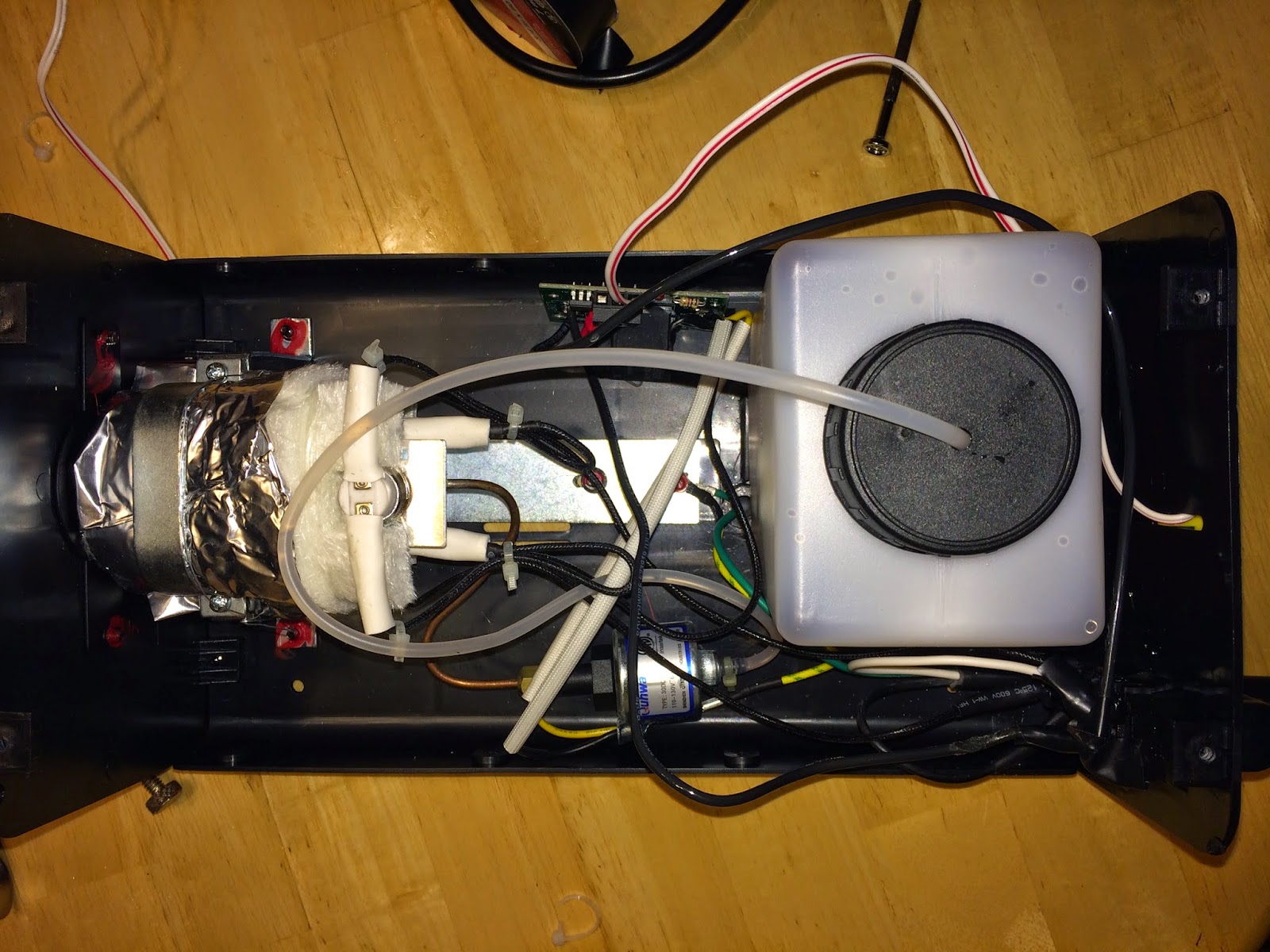
Once everything is soldered up, the only left to do is to run a control wire to the outside of the case and put all the components back in the box prior to closing up:
 |
| Modified smoke machine prior to buttoning up. Note presence of new relay board at the top of the case (with the white two-wire cable running to the rear of the case). |
On the outside of the case, I zip-tied a screw-down terminal block I happened to have on hand. Once buttoned up, this will be the only external evidence that the case was modified and will provide easy access to the digital control lines needed to remotely control the machine.
 |
| Smoke machine rear with added screw-down terminal block |
Conclusion
All-in-all, not bad for one night's work. While there are certainly other ways to approach this problem, for me, this was a quick and easy win using the parts I had on hand given the impending Halloween deadline. Trick or treaters, beware!


No comments:
Post a Comment